Summary: Second of a two-part post on developing a taxonomy of cellular materials. This post focuses on 3D cellular materials. A previous post addressed 2D (prismatic) cellular materials.
In the first part of this two-part post, we introduced a classification scheme for cellular materials that was a synthesis of ideas borrowing from communities spanning the fields of cellular solids, geometry, crystallography and design software. The first part also dived deeper into 2D prismatic cellular materials. In this post, we complete the taxonomy by focusing on 3D cellular materials.
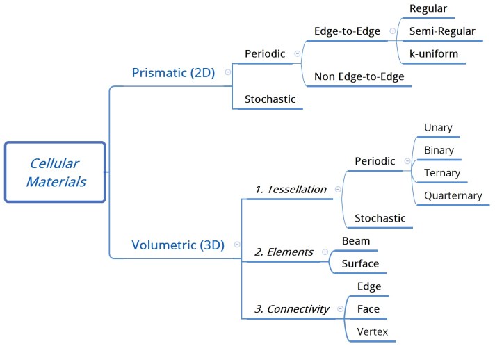
For the sake of consistency, it would make sense to classify volumetric cellular materials purely in terms of tessellation, as we did for 2D materials. However, unlike in 2D, this approach is not sufficient in 3D since it says nothing of the connectivity within tessellated cells. Therefore, as shown in Figure 1, reproduced from part 1 of this post, for 3D cellular materials we propose a different nomenclature strategy that involves 3 specific decisions a designer has to make, regarding the shape of tessellation, the nature of the elements filling the unit cells, and how they are connected relative to the tessellated outline.
1. Tessellation
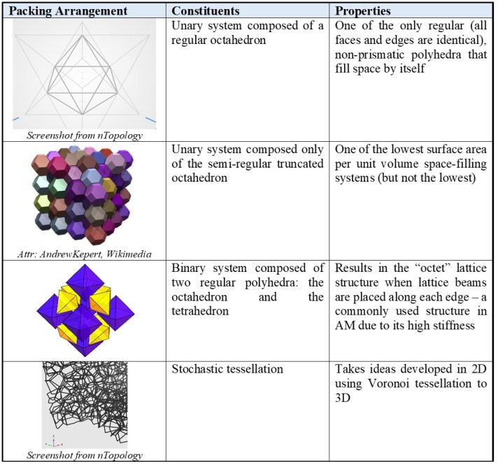
Tessellation is the first of three decisions that a designer has to make when seeking to fill space with 3D cellular structures. As with the prismatic cellular materials, the first level of separation within tessellation is into periodic and stochastic polyhedra. For the former, it is typical to assume only regular or semi-regular polyhedra for reasons of tractability. Within this category, Pearce (1980) identifies 23 different space-filling polyhedra. Discounting the three prismatic polyhedra (cube, triangular prism and hexagonal prism), we are left with 20 space filling systems. These could be composed of one, two, three or four polyhedra and are termed Unary, Binary, Ternary and Quarternary, respectively. Table 1 lists some space filling tessellations that have interesting properties and may form the basis of tessellation for cellular materials with AM for designers. For a more complete study, the reader is referred to the excellent titles by Pearce (Polyhedra Primer and Structure in Nature as a Design Strategy).
Table 1. Examples of 3D space-filling with non-prismatic polyhedra
2. Elements
Tessellation is merely the first in a 3-step process to defining a 3D unit cell. The next step involves deciding what physical elements will occupy that space. At first glance, this may seem trivial, given our proclivity for lattices in AM. However, there are several options for a given lattice beam, as well as alternative ways to fill space that do not involve beams.
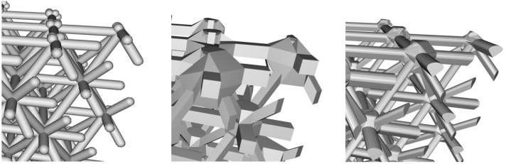
For beam-based lattice structures, the length of the beam is governed by the placement of vertices in space, which we discuss in the next section. However, the beam itself has a cross-section that can take a range of shapes, including a variable section from one end to another. Figure 2 shows three possible cross-sections one can assign to a beam. Depending on the scales involved, such nuances may not be resolvable, but if they are, they become a design variable that can influence behavior as well as manufacturability, such as the teardrop shape in Figure 2 (right), so designed to enable overhanging lattice beams to be self-supporting for processes that need support, such as laser powder bed fusion.
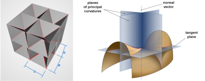
An alternative to beams is to use surfaces in the construction of the unit cell. Here we have two further possibilities – the use of flat surfaces or curved. A particularly interesting use of curved surfaces is the use of minimal surfaces, that have an average curvature of zero at every point on the surface. An example of a flat surface cellular material and the basic minimal surface are shown in Figure 3. Minimal surfaces are energetically favorable ways of weaving surfaces through space and mathematicians have developed several of these surfaces (Schoen, 2012).
3. Connectivity
Once the type of tessellation and nature of the elements are specified, the last step is to integrate the two. This is done through specifying a series of nodal co-ordinates and establishing connectivity between them, or deploying an equation that assigns these to the unit cell. For lattices, an example is shown in Figure 4 for cubic tessellations using beam elements, but with different nodes and connectivity. This form of connectivity can also then be used to define surfaces between edges, one example of which was shown in Figure 4 (left).

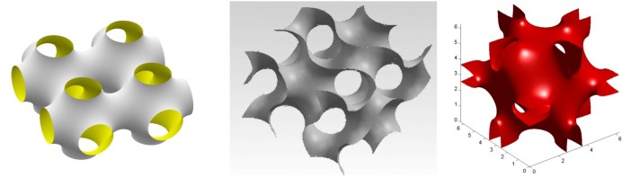
With regard to the previously discussed minimal surfaces, the surfaces of interest from a space-filling perspective are called TPMS, or Triply Periodic Minimal Surfaces. Dating back to 1865, there are now several types of TPMS structures, a selection of which are shown in Figure 5. TPMS structures are developed from governing equations that can be implemented in CAD software. TPMS structures also occur in nature and have been found both in living creatures (sea urchins, the scales on butterfly wings and beetle exoskeletons) as well as in zeolite and some liquid crystals (Han and Che, 2018).
A Note on Nomenclature
There is no agreed upon nomenclature for cellular materials in the AM community at the moment, with researchers using the most colloquial name they can identify for a particular shape. While terms like BCC, octet and Gyroid are increasing gaining traction in the AM design community, there remains the need for a formal nomenclature that can extend to the most general case. Inspired by the nomenclature system used in nTopology’s Element software, the following four step nomenclature scheme is proposed:
- Dimensionality: This involves determination of whether the cell is prismatic (2D) or volumetric (3D)
- Tessellation: The compartmentalization of space into independent volumes of a certain shape
- Elements: The use of beams and/or shells/faces within the tessellated space, and
- Topology: The actual arrangement of the elements within the tessellated space
Four examples of this nomenclature are shown in Figure 6, with the term lattice being used to represent beam elements, and surface for surface/face elements. While close to a comprehensive naming system, it does have the downside of being quite a mouthful. The bee’s honeycomb would thus be called a Hex Prism Edge Surface cellular material. Therefore, when a simpler term is sufficient and popular in the community, it should be used. For all other cases, this nomenclature is proposed.

What of foams, then?
The above classification scheme makes no mention of foams – why is this? There are two reasons: the first has to do with the manufacturing process: foams are perhaps the only cellular material that strongly hint at their method of manufacture in the name itself: most foams are made through foaming processes, i.e. through the generation of gas bubbles in the forming process that creates the void spaces in the foam. Secondly, foams typically have highly stochastic, and somewhat indeterminate geometries with curved walls and edges. Thus, within the constructs of the proposed taxonomy, foams can be considered to be a stochastic tessellation of 3D space with either beam (open cell foam) or surface (closed cell foam) elements.
Having said this, the study of foams and their applications are among the most robust in the field of cellular materials, and there is a lot to borrow when developing ideas for cellular materials in AM, particularly with regard to understanding their properties – but this will have to wait for another post.
~
Thank you for reading, I hope this was useful! To ensure you don’t miss a future post (we do 2 or 3 a month), or to give us your feedback, please connect with us on LinkedIn and/or Twitter.
